🕑 Reading time: 1 minute
Sardar Patel Stadium was renamed as Narendra Modi Stadium on 24th February 2021, also known as Motera Stadium. The cricket stadium is located in the state of Gujarat in India. It is situated on the banks of the Sabarmati river in Motera, Ahmedabad. The stadium is spread across 63 acres of land with a seating capacity of 110,000. The stadium can accommodate 10,000 more people than Australia’s iconic Melbourne Cricket Ground, making it the largest cricket stadium in the world.
The Motera stadium is the home ground of the Gujarat Cricket Association. Despite the immensity of the project, the stadium was constructed within a period of three years. The stadium consists of four team dressing rooms and facilities, 76 corporate boxes, state-of-the-art club facilities with three practice grounds, an indoor cricket academy, and an Olympic-size swimming pool.
The stadium was planned and designed by POPULOUS— a sports-architecture firm based in Australia and was constructed in collaboration with India’s top contractor Larsen & Toubro.
Just like any other stadium, Sardar Patel Stadium follows the exposed-concrete design. While stadiums are generally built with repetitive structural elements, the Sardar Patel Stadium was constructed with precast concrete segments to ensure faster and high-quality construction.
The planning and designing groups discretized the precast components, and a strong emphasis was put on limiting the quantity of components and their joints. This resulted in huge and hefty components with complex and unbalanced geometries.
These attributes complicated the transportation, casting, lifting, and erection of the precast components in the portal frames. Thus, there was a need for the development of innovative structural components during different phases of erection. For each stage, the precast components were precisely planned and designed.

The complex design of the portal frame was characterized by the planners to give a 360-degree view of the cricket field from the seating level (podium level). The podium level is located 12 m above the nearby streets and serves the traffic-free movement for pedestrians to walk towards the upper and lower seating bowls. The seating capacity of each bowl, upper and lower, is 55,000. For the rapid entry and exit of the audience seating in the stadium, two gigantic pedestrian staircases were constructed from street level to the podium level.
Construction of the world’s biggest and largest stadium is a triumph for the construction industry in terms of adopting the biggest precast segments by using detailed and innovative methods and erection techniques.
In this article, we discuss the structural elements, some of the major precast components like the HY and GY columns, radial circumferential beams, vomitory staircases, and the construction features of the Sardar Patel Stadium.
Contents:
1. Structural Elements of the Sardar Patel Stadium
The structural elements of the Sardar Patel Stadium are:
- Upper and lower bowls planned for seating
- A podium level to enter the upper and lower bowls
- Vomitory staircases designed for the entry and exit of the audience from the stadium
- HY and GY columns
- Primary, secondary, and circumferential beams
- Structural steel roof
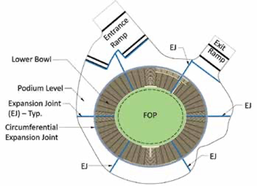
The stadium has an oval and divided into six different sections by expansion joints. Also, the expansion joints were provided to isolate the podium level from ramps. A circumferential expansion joint was provided to isolate the upper and lower bowls. At each expansion joint, twin columns were used to support the components up to the podium level.
The roller boundary condition was formed at expansion joints for each circumferential beam by placing corbels on the primary radial beams at the top of the upper bowl. Similarly, the roller boundary condition was formed at the lower bowl by supporting the lower bowl’s radial beams through the upper bowl columns near the podium level.
The main structural components of the upper bowl comprise Y-shaped columns situated on the circumferential grids G and H and named as GY and HY columns. Primary radial beams are connected to the GY and HY columns.
To reduce the deflection of primary radial beams and the thickness of the slab, secondary radial beams were provided in between. Thus, the podium level consists of primary and secondary radial beams, circumferential beams, and precast hollow-core slab panels.

1.1 HY and GY Columns
The HY and GY columns are lopsidedly molded components characterized by aesthetic and practical constraints. Each column was formed without any joint in between and directly connecting to the radial beam and foundation at the top and bottom, respectively.

1.2 Primary Radial Beam
Primary radial beams are supported by the GY and HY columns in the upper bowl. The lateral support to primary radial beams is provided by the circumferential beams at the column-beam joints. The force transfer mechanism between the column and beam was achieved by providing structural steel components inserted in and stretching out from the columns into pockets of the primary radial beams.
Primary radial beam components were shipped to the place of work on trailers with rubber supports to minimize the stresses on the precast elements. At the place of work, the beams were placed to the necessary point using bespoke spreader shafts. Further, the position of the pocket in the beams was matched with the steel elements of the column and beams were connected successfully to the columns. Beams were held in position by the crane until the high-strength concrete had been filled in the pocket of the beam and the concrete had gained sufficient strength.
1.3 Circumferential Beam
The circumferential beams were not a complete precast segment. Only the middle segment was precast and dowel bars were stretching out from both sides of the middle segment. The remaining portion was filled with the cast-in-place concrete when the circumferential beams were connected to the primary radial beams. This was accomplished by putting the middle segment of the circumferential beam inside steel cages and lifting the whole assembly by the crane, and positioning the assembly in line with primary radial beams components.
Couplers were utilized to fix the strung dowels in the primary radial beam components, with extra strengthening bars provided above the dowels of the circumferential beam components. This technique wiped out the framework requirement and permitted laborers to put concrete 115 feet above the road level. Once the circumferential beam achieved sufficient strength, the steel cage was removed.

1.4 Secondary Radial Beam
Secondary radial beams were put over the corbels provided in the circumferential beam components after the circumferential beam had achieved sufficient strength. Both the circumferential beams and secondary radial beams components were cast with the sleeves, and steel bars were embedded in the sleeves and grouted to resist the transverse loading.
When all the precast elements and cast-in-place concrete had been placed at their designated locations, the entire portal structure was complete. After that, the L-shaped stadia components were lifted into place between the primary and secondary radial beam components to finish the upper bowl.

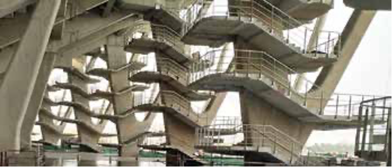
1.5 Vomitory Staircases
Vomitory staircases were provided to access the upper bowl for the audiences. The staircase steps were cantilever from the HY column to create an aesthetically pleasing look. However, the design of such a staircase was very complicated. The staircase was constructed using precast concrete elements and structural steel.
Cantilevered steel beams were provided to support the precast concrete slab for the staircase landing. These cantilevered steel beams were embedded inside the HY column at the predefined location.
1.6 Structural Steel Roof
The structural steel roof of the stadium consists of radial cables, an inner tension ring, an outer compression ring, and a membrane. The radial cables are fully locked between the outer compression and inner tension rings. The membrane is provided to cover the entire roof of the stadium, and it is made up of woven fiberglass fabric coated with polytetrafluoroethylene. The membrane is stretched between the outer compression and inner tension rings.
Separate V-shaped columns were constructed to support the tension and compression rings. These columns are directly supported on the podium level without transferring the forces to concrete bowls. The force between rings and V-shaped columns is transferred through steel tubes connected at the bottom of rings.

2. Construction Stages of the Sardar Patel Stadium
Columns are the major structural elements supporting all the structural components of the stadium. Generally, columns are subjected to shear forces, moments, and axial forces. The forces on the columns were determined using finite element analysis. The components included in the finite element analysis were Y-shaped and V-shaped columns, primary and secondary radial beams, circumferential beams at the lower-bowl level, upper-bowl level, and podium level.
During the erection of the columns and beams, the columns were subjected to major forces. Thus, the analysis of the column during the construction phase became important. Therefore, we are discussing all the construction stages for the most critically loaded HY column.
2.1 Lifting Stage
The HY columns were cast on the precast concrete bed. After the columns achieved sufficient strength, they were transferred to the storage yard. Through the finite element analysis, the predefined points were selected on the HY column for lifting so that minimal stresses can be induced in the columns. Therefore, the HY columns were lifted using hoisting cables to the self-propelled trailers.

2.2 Transportation Stage
Self-propelled trailers were used to transport the HY columns from the storage yard to the area where it would be constructed in the stadium. As the construction site was not uniform, the self-propelled trailers had an inbuilt system of hydraulic lifts utilized to prevent differential movements at the base of the trailer. The finite element analysis incorporated these conditions and the strength and serviceability criteria were checked for the differential movement.

2.3 Erection Stage
The erection stage is the most critical stage for any structural element, so are HY columns. A bespoke C-shaped clamp was used to pivot the HY column from horizontal to vertical position. This clamp was fixed simply above the focal point of the precast segment, as this permitted the component to be pivoted effectively with minimal push and direction.
Two cranes were used to erect each of the HY columns. One crane was associated with dealing the connection with the C-shaped clamp and the other crane was giving the direction to the bottom end of the column by rotating it. The column was rotated from horizontal to vertical direction by releasing the bottom end held by the crane.

2.4 Post-erection Stage
After shifting to the vertical position, the column was placed on the foundation elements. The connection between column and foundation was made using corrugated sleeves. These sleeves were cast in the column and connected to the foundation through dowel bars.
After connecting the dowel bars through the sleeves, the sleeves were grouted. The grout material was a high-strength grout intended to accomplish the necessary strength in 24 hours to reduce the crane handling time.
After the connection between the column and the foundation was made, a temporary steel truss tie was connected to the column in the lateral and circumferential directions. The steel truss tie was provided at the intermediate level between the nearby HY columns. The reason for providing the steel truss tie was to support a 35 m long cantilever projected from the foundation as an HY column.
After the primary and secondary radial beams were connected to the HY columns, the temporary steel truss ties were removed as the complete portal frame action was accomplished.

FAQs
The Motera stadium is situated in seismic zone-III as per the Indian Code IS 1893-2002.
The dead load, live load, wind load, and the earthquake load were calculated as per the following IS codes:
IS 875 (Part 1) – 1987
IS 875 (Part 2) – 1987
IS 875 (Part 3) – 2015
IS 1893 – 2002
The design life of the Motera Stadium is 100 years.
The structural elements used in the construction of the Sardar Patel Stadium are described below:
1. Upper and lower bowls planned for seating
2. A podium level to enter the upper and lower bowls
3. Vomitory staircases designed for the entry and exit of the audience from the stadium
4. HY and GY columns
5. Primary, secondary, and circumferential beams
6. Structural steel roof
The seating capacity of the upper and lower bowl is 55,000 each. Thus, the total seating capacity of the Sardar Patel Stadium is 1,10,000 persons.
Read More
Statue of Unity: Structural and Construction Features of the World’s Tallest Statue
Taj Mahal: Construction of its Invincible Foundation
The Colosseum: Construction of the World’s Largest Amphitheater