🕑 Reading time: 1 minute
Moment distribution method offers a convenient way to analyse statically indeterminate beams and rigid frames.In the moment distribution method, every joint of the structure to be analysed is fixed so as to develop the fixed-end moments. Then, each fixed joint is sequentially released and the fixed-end moments (which by the time of release are not in equilibrium) are distributed to adjacent members until equilibrium is achieved. Moreover, the moment distribution method in mathematical terms can be demonstrated as the process of solving a set of simultaneous equations by means of iteration. Added to that, it falls into the category of displacement method of structural analysis. Finally, moments distribution method of structural analysis is thoroughly presented in the following sections in addition to provide solved example.Contents:
Basic definitions of terms in moment distribution method of structural analysis
Fixed end moments
Fixed end moments are the moments produced at member ends by when the joints are fixed. Table 1 provides equations for fixed end moment computations. Table 1: Fixed end moment equations |
 |
 |
 |
 |
 |
 |
 |
Flexural stiffness
The flexural stiffness (EI/L) of a member is represented as the product of the modulus of elasticity (E) and the second moment of area (I) divided by the length (L) of the member. Additionally, what is needed in the moment distribution method is not the exact value but the ratio of flexural stiffness of all members.Distribution factors
Distribution factors can be defined as the proportions of the unbalanced moments carried by each of the members.Carryover factors
Unbalanced moments are carried over to the other end of the member when the joint is released. Added to that, the ratio of the carried-over moment at the other end to the fixed-end moment of the initial end is the carryover factor. Lastly, For prismatic members, the carryover moment in each span has the same sign as the distribution end moment, but is one-half as large.Sign convention
Any moment acting clockwise is considered to be positive. This differs from the usual engineer's sign convention, which employs a Cartesian coordinate system with positive x-axis to the right and positive y-axis up, resulting in positive moment about the z-axis being counterclockwise.
Fig.1: Moment distribution and common sign convention comparison
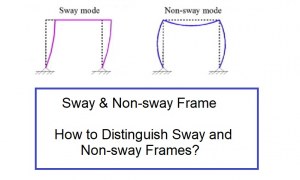
Framed structures
Framed structures with or without sides way can be analysed using the moment distribution method.Moment distribution analysis procedure for beams
1. Restrain all possible displacements. 2. Then, calculate Distribution Factors: The distribution factor DFi of a member connected to any joint J is where S is the rotational stiffness , and estimated by:
 3. After that, determine carry-over factors
The carry-over factor to a fixed end is always 0.5, otherwise it is zero.
4. Next, calculate Fixed End Moments. (Table 1).
These could be due to in-span loads, temperature variation and/or relative displacement between the ends of a member.
5. Then, do distribution cycles for all joints simultaneously.
6. Each cycle consists of two steps:
Distribution of out of balance moments Mo, where
3. After that, determine carry-over factors
The carry-over factor to a fixed end is always 0.5, otherwise it is zero.
4. Next, calculate Fixed End Moments. (Table 1).
These could be due to in-span loads, temperature variation and/or relative displacement between the ends of a member.
5. Then, do distribution cycles for all joints simultaneously.
6. Each cycle consists of two steps:
Distribution of out of balance moments Mo, where
 Then;
Then;
Me: external moment applied to the joint (if any)
Mo: total out of balance moment at the joint
FEMi: fixed-end moment
Mi: moment distributed to any member
DFi: distribution factor of member i
7. Calculation of the carry over moment at the far end of each member.
The procedure is stopped when, at all joints, the out of balance moment is a negligible value. In this case, the joints should be balanced and no carry-over moments are calculated.
8. Finally, calculate the final moment at either end of each member.
This is the sum of all moments (including FEM) computed during the distribution cycles.
Analyzing statically indeterminate beam using moment distribution method
- Members AB, BC, CD have the same length
 .
. - Flexural rigidities are EI, 2EI, EI respectively.
- Concentrated load of magnitude acts at a distance from the support A.
- Uniform load of intensity acts on BC.
- Member CD is loaded at its mid-span with a concentrated load of magnitude .

Fig.3: Indeterminate beam example
Fixed-end moments
In the following calculations, counterclockwise moments are positive:Distribution factors


 The distribution factors of joints A and D are DAB = DDC = 1.
Carryover factors
The carryover factors areDetails of calculations
Table 2: details of moment distribution calculations| Joints |
A |
B |
C |
D |
||||
| Distribution factors | 0 | 1 | 0.2727 | 0.7273 | 0.6667 | 0.3333 | 0 | 0 |
| Fixed-end moments | 14.700 | -6.300 | 8.333 | -8.333 | 12.500 | -12.500 | ||
| Step 1 | -14.700 | -7.350 | ||||||
| Step 2 | 1.450 | 3.867 | 1.934 | |||||
| Step 3 | -2.034 | -4.067 | -2.034 | -1.017 | ||||
| Step 4 | 0.555 | 1.479 | 0.739 | |||||
| Step 5 | -0.246 | -0.493 | -0.246 | -0.123 | ||||
| Step 6 | 0.067 | 0.179 | 0.090 | |||||
| Step 7 | -0.030 | -0.060 | -0.030 | -0.015 | ||||
| Step 8 | 0.008 | 0.022 | 0.011 | |||||
| Step 9 | -0.004 | -0.007 | -0.004 | -0.002 | ||||
| Step 10 | 0.001 | 0.003 | ||||||
| Sum of moments | 0 | -11.569 | 11.569 | -10.186 | 10.186 | -13.657 | ||
Results
Moments at joints determined by the moment distribution methodShear force and bending moment diagram
Table 3 provides shear and moment diagram for the analyzed beam. Note that the moment distribution method only determines the moments at the joints. Moreover, developing complete bending moment diagrams require additional calculations using the determined joint moments and internal section equilibrium. Table 3: shear force and moment diagram for the analyzed indeterminate beamShear force diagram
 |
Bending moment diagram
 |